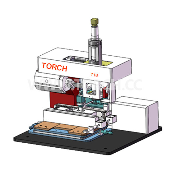
Submicron High Precision Mounter T1S
- Introduction:
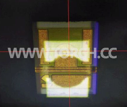
TORCH Submicron high precision mounter T1S is a multifunctional mounter, providing the mount accuracy up to ≤ ± 1 μm. It is suitable for mounting all kinds of flip chip and common chip, and can handle the minimum chip spacing as low as 50 microns. The device has a high precision and high stability spectrometer optical fixed alignment system, which can simultaneously display the overlapping image of the suction head and the chip on the computer screen in real time, and can complete the chip mounting without graphics (PR) programming.
TORCH Submicron high precision mounter T1S is a chip bonding machine for R & D and production, which can complete high-precision laser bar assembly, including bar to sub substrate and sub assembly to heat sink placement and bonding. In contrast to a single laser tube, a laser bar consists of multiple edge emitting single tube lasers on a single silicon bar. The output power of the beam is improved significantly and the application range is expanded. Laser bar is a high-power product, which is used in the situation of requiring small and efficient light-emitting unit. Laser bar is mainly used as the pump source of high-power laser optical resonator, and it is often used in the medical field.
Basic information of equipment:
Purpose: High power semiconductor laser bar chip welding.
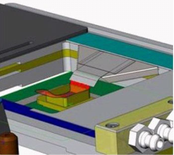
System composition: equipment host, side camera, pressure module, mounting system with rotation, precision correction tool, heating system, inert gas protection module, self balancing nozzle or module, field of view expansion module, computer control system, etc.
Mounting accuracy: the alignment accuracy after mounting and welding is ≤ ± 1 μm.
Mounting speed: welding standard bar speed ≥ 15 pieces / hour.
Introduction of equipment technical composition:
1. Provide stable support for equipment, including basic mechanical and optical systems. With a set of computer display and control system, to complete the process including flip chip, face up chip eutectic soldering, hot plate reflow soldering and so on.
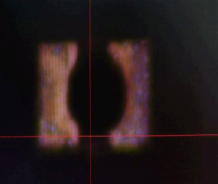
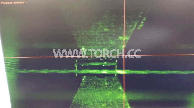
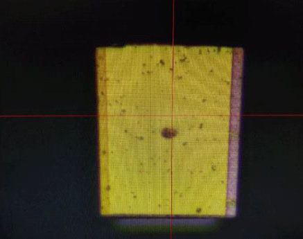
2. There is a side camera to provide the observation image of chip side alignment, so as to ensure the accuracy of welding alignment and the controllable guarantee of pressure. It has the function of chip side observation.
3. The equipment needs to provide appropriate mounting pressure: the maximum mounting pressure is not less than 30N, the mounting pressure parameters are adjustable, the adjustment resolution is not less than 0.3N, the pressure working curve can be compiled, the pressure closed-loop control can be set, and the pressure and allowable range can be set.
4. The device needs to provide the rotation function to ensure the parallelism between the chip and the substrate during the placement, so as to avoid obvious deflection. The accuracy requirement is that the alignment accuracy between the chip and the reference line is ≤ ± 1um.
5. Provide heating system that can control heating time and speed, heating range includes normal temperature to 400 ℃, heating accuracy ≤ 2%.
6. Provide protective gas for solder, heat sink and chip during chip burning and soldering to prevent oxidation and other adverse phenomena.
7. It has a digital vacuum sensor, which can sense whether there is a chip adsorbing on the chip head to prevent the chip from losing.
8. Configure accuracy calibration tool.
9. Configure the visual field increasing observation module, so that the camera can move: the X-axis moving range is not less than 40mm, and the Y-axis moving range is not less than 10mm.
10. The equipment is equipped with self balancing suction nozzle, and a reference drawing is provided for customers' reference.
Picking process:
1. Full automatic operation.
2. The components are fragile and have optical sensitive areas that cannot be touched.
3. Edges and faces of complex components.
4. Full scale amplification required for laser bar and sub substrate
Welding:
1. Good thermal properties require perfect coplanarity.
2. The set protrusion distance requires the highest precision after bonding.
3. Automatic two-point alignment ensures perfect angle accuracy.
4. Fast heating capacity to shorten process time.
5. Solder is easy to oxidize, so inert gas protection function should be integrated.
6. Different temperature curves for different solders are required for stacking patches (laser bar to sub substrate)
Inert gas protection:
1. Guarantee that the tin and indium solders are in a specific protective gas.
2. Formic acid as process gas can prevent and reduce oxidation.
3. Automatic formic acid gas supply.
4. A variety of standard and customized inert gas protection chamber, controllable inlet and outlet.
5. Automatic control of air intake time and flow to ensure process repeatability.
Process:
Place the sub-substrate on the heatable working platform

Pick up the laser bar from the stock box
The laser bar is aligned with the sub substrate
Place the laser strips on the subsubstrate and bond them (e.g. gold tin solder)
Pick up the welded subassemblies
Place the heat sink on a heatable work platform (e.g. CS-MEUNT)
Match the subcomponents with the heat sink
Place the subcomponents in reverse heat sink and bond them (such as indium solder)
Bonding the N-pole connector to the upper surface of the laser bar (e.g. indium tin solder)
To complete the process
Application scope:
1. Flip chip bonding (face down).
2. High precision chip bonding (face up).
3. Laser diode, laser bar welding.
4. VCSEL, PD, lens package.
5. High end led packaging.
6. Micro optical device packaging.
7. MEMS packaging.
8. Sensor package.
9. 3D Packaging.
10. Wafer level package (W2W, c2w).
11. Chip to glass substrate, chip to flexible substrate mounting.
Technical parameters:
| No | Technical index | Parameters |
| 1 | Mounting accuracy | ≤±1μm |
| 2 | Mounting chip size (minimum) | 0.125*.125mm |
| 3 | Minimum view | ≥0.45mm×0.55mm |
| 4 | Z-axis move rang and accuracy | ≥10mm |
| 5 | Heating temperature | ≥400℃ |
| 6 | Heating rate | ≥20℃/S |
| 7 | Heating area | ≥50mm×50mm |
| 8 | Placement pressure | ≥0.3~30N |
| 9 | Configuration of formic acid gas protection | With basically closed inert gas protection chamber, gas flow can be adjusted |
| 10 | Configure chip angle fine adjustment function | It can fine tune the chip angle ≥ 2 ° |
| 11 | Configure side video viewing function | With the function of observing the side of the chip |
| 12 | Configure the field of view increasing observation module, sothat the camera can move | X-axis movement range ≥ 40mm, Y-axis movement range ≥ 10mm |